Aux position on ignition key
13 posts
|Page 1 of 1
Aux position on ignition key
I thought the first stop on the ignition key was there to operate the car stereo. I've just been poking around on the ISO connector (installing a new stereo) and nothing "lights up" as +12V when the key is in this first position. The connection marked Ign. on the stereo does get 12V when the key is turned to the ignition position, but if I want to sit and listen to the stereo I don't want all the warning lights and engine electrics on!
-
Adrian

Rusty - used to have it wired like that but my new system draws 0.1 amps when connected together. Too much drain on the battery.
Robbie - thanks for the link. I see that mod. takes the "key out" position and inverts it to supply power in all the other positions. What a pain! The wiring for "later models" in the back of Haynes shows a connection to position I so I guess some people don't have this problem.
Andy - is yours a "later model" then? I can't see how you can do it with just a diode & relay...
-
Adrian
I did it with my cavalier sory should have said that.
But calibras are the same, i take it they have parking lights?
The parking light feed is live at 0 and off at I
I took advantage of this to switch a low power SPDT relay so when the key was at 0 the live worked the relay to switch to the contact were no feed was going, then at 1 the relay turned off and the contacts moved to the other position sending a 12v feed to the radio which is joined to the inition feed. However this new feed going 12v will cause your ignition to come on from backflow of current so you need to fit the diode to the ignition wire so it can only flow into the radio and not back through the wire
-
Andy M
Right so here's a summary of the problem for anyone else looking into this: Car stereos often have two supply wires; one is a permanent connection to 12V, the other is an "enable" to switch on and off from the ignition key. My new stereo has a built-in Bluetooth handsfree function and if both these connections are made to a permanent 12V connection, the unit draws 100mA or so - too much for standby.
Although the Vauxhall Calibra/Cavalier ignition key has an Aux. position (I) which is engaged before the ignition is switched on at position (II) there is no contact on the back of the switch! This would be a nice contact to have to allow a radio to be operated without the engine on. However, there is a contact which is made to 12V when the key is out, and not made in all other positions - including (I). If we had the "inverse" of this, so that a connection to 12V was made in all positions other than when the key was out, then this would be perfect for enabling the radio,
This can be done with a simple transistor inverter driving a relay from the parking light terminal on the back of the ignition switch. Here's the schematic:
The back if the Ignition switch can be accessed by removing all the screws holding the two halves of the cowling together. A small grey wire connects 12V to the parking lights via the turn indicator switch. I find this an annoying feature anyway so I cut this wire and insulated the end disappearing into the loom. The other end going into the switch is then connected to the Base of the transistor per the schematic above.
Physically I made the circuit by assembling all the parts on top of the relay. The transistor is superglued into position to make assembly of the other parts easier. Having finished assembly and testing it in circuit I insulated it all by covering the components in silicone rubber. The grey wire goes to the back of the ignition switch, the green to chassis and the top red to +12 (its got a blue stripe in case you're wondering how I know which is which!) and the other red goes to the stereo's ignition input.
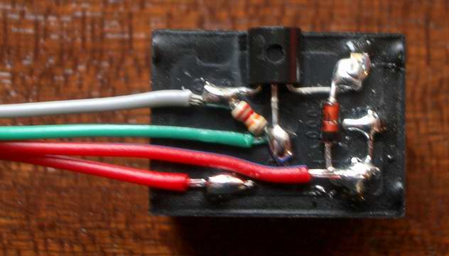
The circuit draws half a milliamp (500uA) when the key is out so won't drain the battery when the car is left standing for long periods. All the components can be bought from <a href="http://cpc.farnell.com/" target="_blank">http://cpc.farnell.com</a> (a good value electronics catalogue). Here's the order codes
I think for just over £1 it makes a great improvement to things!
Although the Vauxhall Calibra/Cavalier ignition key has an Aux. position (I) which is engaged before the ignition is switched on at position (II) there is no contact on the back of the switch! This would be a nice contact to have to allow a radio to be operated without the engine on. However, there is a contact which is made to 12V when the key is out, and not made in all other positions - including (I). If we had the "inverse" of this, so that a connection to 12V was made in all positions other than when the key was out, then this would be perfect for enabling the radio,
This can be done with a simple transistor inverter driving a relay from the parking light terminal on the back of the ignition switch. Here's the schematic:
The back if the Ignition switch can be accessed by removing all the screws holding the two halves of the cowling together. A small grey wire connects 12V to the parking lights via the turn indicator switch. I find this an annoying feature anyway so I cut this wire and insulated the end disappearing into the loom. The other end going into the switch is then connected to the Base of the transistor per the schematic above.
Physically I made the circuit by assembling all the parts on top of the relay. The transistor is superglued into position to make assembly of the other parts easier. Having finished assembly and testing it in circuit I insulated it all by covering the components in silicone rubber. The grey wire goes to the back of the ignition switch, the green to chassis and the top red to +12 (its got a blue stripe in case you're wondering how I know which is which!) and the other red goes to the stereo's ignition input.
The circuit draws half a milliamp (500uA) when the key is out so won't drain the battery when the car is left standing for long periods. All the components can be bought from <a href="http://cpc.farnell.com/" target="_blank">http://cpc.farnell.com</a> (a good value electronics catalogue). Here's the order codes
- Code: Select all
T1 BC212    SC06082        0.06p
R1 22K        RE.125CF22K    0.21p (for minimum of 10)
D1 1N4148    SC06005        0.01p
10A relay    SWJS1A12V    0.94p
I think for just over £1 it makes a great improvement to things!
-
Adrian
<!--QuoteBegin-RobbieV+--><div class='quotetop'>(RobbieV)</div><div class='quotemain'><!--QuoteEBegin-->If you ever get bored and decide to make a few of those put me down for one as i aint got a clue on making those :icon_mrgr<!--QuoteEnd--></div><!--QuoteEEnd-->
Aw, are you sure you couldn't put it together? I'd love to help out but it's the time that costs the money. The parts might only be a pound or two (including the wire and other materials) but to cover the time it would take would require something more like a tenner for me to do it. That's why I put up a detailed description so people could DIY
Aw, are you sure you couldn't put it together? I'd love to help out but it's the time that costs the money. The parts might only be a pound or two (including the wire and other materials) but to cover the time it would take would require something more like a tenner for me to do it. That's why I put up a detailed description so people could DIY
-
Adrian
13 posts
|Page 1 of 1
Who is online
Users browsing this forum: Bing [Bot] and 21 guests